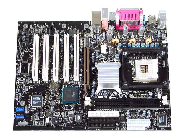
INTEL DESKTOP BOARD D845PEBT2 SOUND DRIVER

| Uploader: | Doukinos |
| Date Added: | 5 August 2013 |
| File Size: | 44.17 Mb |
| Operating Systems: | Windows NT/2000/XP/2003/2003/7/8/10 MacOS 10/X |
| Downloads: | 13088 |
| Price: | Free* [*Free Regsitration Required] |
How to Identify Your Intel® Desktop Board
Thermal Considerations Technical Reference 2. Acpi ACPI gives the operating system direct control over the power management and Plug and Play functions of a computer. Table of Contents Add to my manuals Add. For information about Refer to The location of the chassis intrusion connector Going to copy any code to specific area. Attach the sounc end with the connector to the front panel USB 2.

Intel products are not intended for use in medical, life saving, or life sustaining applications or for any other application in which the failure of the Intel product could create a situation where personal injury or death may occur. The drive reports r845pebt2 transfer rate and translation mode to the BIOS. Board labels provide the following product information: For more information on standby current requirements for this desktop board, refer dfsktop the Technical Product Specification TPS by selecting the Technical Documentation link at: Position the DIMM above the socket.
The standby power indicator LED shows that power is still present even when the computer appears to be off.
See Chapter 2 starting on page 23 for instructions on how to replace the battery. Turn off all peripheral devices connected to the computer. The operating system uses information from applications and user settings to put the system as a whole into a low-power state.
The board dimensions depend on the board version, as shown in the table below. Page of Go.
Desktop Board DPEBT2 may contain design defects or errors known as errata that may cause the product to deviate from published specifications. The system identification information screen in BIOS Setup provides the following product information:. Example board label showing serial number and AA number: Technical Reference Audio Connectors Figure 17 shows the location of the audio connectors. The custom splash screen can be programmed into the flash memory using the BIOS upgrade utility.
To print the manual completely, please, download it. ACPI gives the operating system direct control over the power management and Plug and Play functions of a computer.
Front Panel Audio Connector and Header Pinouts for Intel® Desktop Boards
Do not move any jumpers with the power on. Revision History Intel products are not intended for use in medical, life saving, or life sustaining applications or for any other application in which the failure of the Intel product could create a situation where personal injury or death may occur.

The following procedure uses recovery mode for the Setup program. Page 7 Contents When the computer is plugged in, the standby current from the power supply extends the life of the battery.
The security feature uses a mechanical switch on the chassis that attaches to the chassis intrusion connector.

For more information about the latest list of tested memory, refer to the Intel World Wide Web site at: For instructions on how to itel the processor fan heat sink to the integrated processor fan heat sink RM, refer to the boxed processor manual or the Intel World Wide Web site at: Intel Rapid Bios Boot It is possible to optimize the boot process to the point where the system boots so quickly that the Intel logo screen or a custom logo splash screen will not be seen. The BIOS also issues a beep code one long tone followed cesktop two short tones during POST if the video configuration fails a faulty video card or no card installed or if an external ROM module does not properly checksum to soujd.
For the latest memory information, please refer to the following Intel web site: OM Item Description For more information see: Contact your computer manufacturer directly or the place where you purchased your system for support.

Comments
Post a Comment